wearable devices Flex PCB application
China Flex PCB Manufacturing, Shenzhen Flex PCB Manufacturer, Making Flex Circuit boards
Flex PCB Contract manufacturer, PCB Fabrication, Turnkey assembly services
Buy Flexible Print circuit board, customer: /USA/UK/Canada/South Africa...
Flex PCB Supplier Shenzhen, China, Flex PCB Manufacturer, Turnkey services
-
PCBSINO is the Top 5 PCB manufacturer company in China.
PCBSINO do rapid Flexible PCB Prototype within. we can make Flexible Print circuit boards and Rigid circuit boards, Flex and Rigid Flex PCB, single side, double side, multilayer Flexible print circuit board
PCBSINO making many type electronic product for our customer, Our turkey services team can source original components part for your project(Digikey/Mouser/RS...), senior Electronic engineer will follow each step of the production to solve any PCB problem and our team will do final function test in PCB house.
Flex PCB |
|
Rigid FlexPCB Rapid Prototype |
| Flex PCB |
|
prototype of Flex PCB |
| Flex Prototype |
|
Rigid-Flex PCB Rapid Prototype China, |
Turnkey Services |
|
Turnkey Flex PCB Assembly Services, |
| PCB assembly |
|
Print circuit board Manufacturing, Turnkey assembly |
| PCBA Assembly |
|
SMT Assembly, EMS/OEM supplier China |
wearable devices Flex PCB application
-
wearable devices Flex PCB application
Printed circuit boards (PCBs) used in most electronic products are basically rigid plates to connect circuitry. But demand for flexible PCBs (or flexible circuits) is rapidly increasing thanks in large part to the burgeoning wearable device market.
Perhaps the largest segment of that market is the healthcare industry where wearable devices will be used to collect all varieties of physiological data for diagnosis and study, as well as personal health use.
Already wearables are available to monitor heart rate, blood pressure, glucose, ECG, muscle movement, and more.
Those wearable devices present a number of difficulties for PCB designers that rigid boards do not. Here are some of those problems and what designers can do to alleviate them.
By definition, wearable products must be small and unobtrusive. In the past, a medical “wearable” such as a Holter monitor included a fairly large external device with a neck strap or belt mount. The new wearables are small and attach directly to the patient with no or few external wires. They collect a variety of data and can even process some analyses.
An unobtrusive device attaching directly to the patient dictates flex circuitry and very dense layouts. In addition, the board shapes are often circular or even more unusual shapes, calling for clever placement and routing. For such small and densely-packed boards, a PCB tool that is optimized for rigid-flex designs makes handling odd shapes much easier.
Careful with the Bend
The point of using flexible circuitry is to be able to shape the final assembly by bending the flex. This presents a number of problems that are not encountered on rigid boards. Bending produces stresses that do not occur with rigid boards. Most PCB tools have tools that allow you to optimize the flex circuitry. To avoid problems with bending forces, here are four tips when design flex:
Don’t use 90° bends on traces: The corners of traces endure more bending stress than straight paths. To avoid delamination problems over time, use straight paths or if traces must change direction, use curves or piecewise-linear curves rather than anything approaching 90°.
Stagger traces on double-sided flex: when traces are run on top of each other on double-sided flex circuits causes uneven distribution of the tension. Instead, traces should be staggered. This also improves the flexibility.
Use teardrops to improve strength and yield: The flexibility of the substrate can lead to delamination over time if not controlled. Instead of circular pads, teardrop pads can be used to add additional material, providing greater strength to the pad to prevent delamination. The teardrops also provide greater tolerance for drilling.
Support your pads: The copper on a flexible substrate is more likely to detach than on a rigid board because of the bending. In addition, the adhesion of copper to the substrate is not as good as on an FR4 PCB. Fabricators suggest through-hole plating and anchor stubs for SMT mounting pads. They also suggest reducing coverlay openings as much as possible.
Because the human hand is larger than the wrist, these devices usually need to be able to separate and expand when putting them on or taking them off. This is where flex circuitry can be incorporated to get electrical signals across flexing areas of the band. The challenge with a flex circuit incorporated into a wristband is that flex circuits don’t like to bend in more than one dimension at any one time. The wristband manufacturer really cannot control how the end-user will remove the device from their wrist. Since most end-users are unaware of the internal workings of the wristband, they may pull and twist the band from their wrist, which can introduce torsional forces. It is important to factor in these torsional forces, along with the single axis-bending forces, when designing the flex and selecting materials.
Another hurdle to overcome in wristband applications is the overmolding process. Flex circuits get very soft and fragile when heated. Heat and pressure from an injection overmolding process can be very damaging to a flex circuit. The flex must be properly supported and the overmolding time and temperature carefully monitored for this to be successful.
Foot-worn sensors. Moving to the other extremities, I have seen many applications for devices and sensors worn on the foot/ankle or in a shoe. These devices are designed to capture everything from the number of steps during an exercise run to diagnosing how irregularities in a person’s stride may cause back/spinal problems. As mentioned, flex circuits do very well when flexed in only one dimension at a given time, so while the bottom of a shoe (inside the shoe of course) can be a hostile environment, flex circuits seem to do a pretty good job and can operate reliably for extended periods of time.
The main hurdle encountered with most of these applications is trying to get data or signals from the flex in the sole of the shoe out to the data-capture electronics. The human ankle is a tough act to follow mechanically, and a flexible circuit does not tolerate the complex movements in multiple axes an ankle tends to serve up. To make connections from a flex circuit inside a shoe to the outside world, I recommend using standard wire with the most elastic insulation available. I have seen some silicone-coated flat cable wiring that seems to hold up pretty well in this application. Obviously, incorporating Bluetooth into the shoe device and skipping past the ankle with RF would be the best choice. One last comment on flexible circuits and its projected lifespan inside a shoe: Even after centuries of refinement, shoes don’t last forever. Don’t ask a flex circuit that is just a few thousands of an inch thick to last forever either.
Typically, a rigid-flex design has the electronic components mounted to the rigid boards, then interconnected by flexible circuits. The flex circuits let the assembly to be bent to fit the assembly into the product enclosure.
The majority of PCBs designed today are basically rigid plates to connect circuitry. But, wearable devices present a number of difficulties for PCB designers that rigid boards do not, including:
Conventional rigid PCBs come in many shapes and sizes, though most are square or rectangular. Board thickness varies from 31 to 93 mils thick and even thicker. Wearable PCBs, on the other hand, come in a variety of odd shapes to suit an application. They are considerably smaller, with sizes ranging from a quarter to a dime or even a shirt button.
Wearables can contain a combination of rigid and flex circuitry or flex circuitry alone. The circuits for most wearables consist of two to four layers of flexible polyester or polyimide. However, the circuitry for newer wearable applications is expected to have 12 to 14 flexible layers of various materials.
Attaching flex circuits to a rigid board calls for a special process. Because rigid and flex circuits have different coefficients of thermal expansion, heat-curing adhesives are used to join them.
Pull testing of soldered components is rarely done with conventional rigid PCBs, but it is often done on flexible circuits for wearable electronics. Such testing is performed to ensure that soldered joints on flex circuits are strong enough to withstand a designated number of bending cycles.
Sensors and Packaging
Sensors are rarely used in conventional PCBs, but they are an increasingly popular feature in wearable electronics. Such sensors are used to measure things like heart rate, blood pressure, and distance traveled. According to market research firm IDTechEx, 3 billion wearable sensors will be in use by 2025, including chemical, stretch, pressure, optical, biopotential and inertial measurement sensors. More than 30 percent of wearable sensors on the market in 2025 will be newly introduced technologies.
A critical part of the assembly process for wearable flex circuits is to test these sensors to their maximum limits. It’s also important to create sufficient soldering pads so that the sensor sits flat on the flex circuit and can contact the skin to collect data.
Electronic device packaging for wearable PCBs also requires careful scrutiny. Just as with conventional PCBs, wearable PCBs continue to shrink. OEMs demand higher performance in ever smaller form factors.
Wearable technology is something that quite a large number of people use every day—and don't even realize they are using it. The term sounds complicated and highly technical, but in reality, most wearable technology devices in use today include products like smart watches (Apple iWatch or the Kickstarter-created Pebble) and activity trackers (such as Fitbit and Garmin's Vivosmart.) Wearable technology has improved lives for a lot of people in rather straightforward ways—so far. However, the technology is new. Wearables are beginning to garner a lot of attention for their potential to do more than just tracking steps and controlling Pandora playlists.
In the future, it is entirely possible that wearable technology and flex circuits could play a major role in the medical industry. In fact, these devices have already begun showing up in certain medical settings. We will discuss a few of the ways that wearables have and could impact medicine.
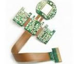
Figure 1: Example of a flexible circuit board.
To address the technology, a common thread that most of these devices share is that they require a flex circuit board. A flex or rigid flex circuit board is a critical component for these devices to be able to operate correctly. Furthermore, flex circuits offer improvement or reduction in packaging requirements. In other words the size of the unit can be reduced by using flex and rigid flex as opposed to other methods of interconnect making the device more portable/wearable. A lot of times a flex or rigid flex must be used to meet design size requirements.
Coming around the bend
Regardless of the application, a flex circuit must be pliable and bendable, but the question is: How pliable and bendable can it be? The jury is still out on the preciseness of bendability (or "bendableness"). As of this writing, the IPC is being rather conservative with its call. So, in essence, the exact definition or gauge of bendability hasn't been pinned down and probably won't be due to its nebulous nature. The best advice given is to rely on an experienced EMS Provider that has several wearable/IoT PCB designs under its belt and has a storehouse of critical nuances associated with flex circuit bendability.
Having said this, it's good to know terms like bend radius, bend ratio, and strains, all of which are inextricably intertwined. Bend radius, as the name implies, is how far you can bend that flex circuit before something breaks or incurs a latent fracture. It's also necessary to know that the measurement of the bend radius is performed from the bend's underside surface. Again, it's advisable to partner with a savvy EMS Provider to analyze and resolve bend radius questions and issues.
A rigid-flexible PCB product can support bending with its structure, so it can be designed in 3-D which assures the manufacturing of small sized products. In addition, there is no signal loss due to the reduced wire length or the contact resistance, and it is suitable for the latest smart devices that require high-speed signals. Our company is providing high density/quality rigid flexible PCB products suitable for Smartphones, Wearable devices and Tablet PCs.
The second term, bend ratio, takes into account the ratio of the bend radius to the thickness of the flex circuit. For example, the bend ratio for a multi-layer flex circuit for a medical electronics wearable device is at least 20:1. By comparison, for the single and double-sided flex circuits the bend ratio should be at least 10:1. Tighter bends may create the risk of circuit damage. It's always preferable to use more gradual angles rather than a right angle bend with a sharp radius. Bend radius is calculated by measuring the distance from the inside surface of the bend to the center of the radius.
It's also important to know there are two aspects associated with flex circuit bending. One is static or one-time bending; the other is dynamic flex involving multiple bending operations. The bend radius for static bending should be at least 10 times the thickness of the circuitry and the strain on the critical layers should be 2.2% or less. On the other hand, the bend radius for dynamic flex circuitry should be 25 times or less.
Medical Wearables Tend to be Single Point Solutions
One thing to keep in mind is that while the consumer market is pushing wearables to do more and more (look at the latest versions of the fitness trackers and how many extra features they include, for instance,) the wearable medical market is going in the opposite direction. Most medical wearables tend to be one solution devices. For example, a medical wearable will track "just insulin levels" or "just steps walked." Just because these devices only monitor one number does not make these devices any less effective or efficient. In fact, this was done more to ensure that the data collected is useful data, and not tarnished because the instrument is trying to do too much with too small of a device.
With the trending and rapidly expanding wearable devices market, technologies and processes in the EMS industries have seen changes and increased demand for different types of products. One of these products that has experienced changing demands is the printed circuit board.
Flexible electronics, commonly known as flex circuits, are electronic circuits that are mounted on flexible substrates made from plastics such as polyether ether ketone (PEEK), polyimide, and transparent conductive polyester film. The primary advantages of these circuits are that they can be conformed to a particular shape during manufacture or able to flex during use. Flex circuits are available in a variety of specific types, with single-sided flex circuits and rigid-flex circuits being some of the most common types.
Flex circuits are most often used in applications where the usefulness of a rigid circuit board is limited due to requirements for flexibility, production constraints, or space savings. For example, the switch matrix in a modern keyboard is almost always a flex circuit. These circuits typically connect electronic components such as capacitors, integrated circuits, and resistors with passive wiring structures. One of the more common uses for flex circuits in recent years is the use of them in wearable devices.
As a result, chipmakers are packing more electronics in smaller pieces of silicon to create such products as systems on a chip (SOC), micro ball-grid arrays (BGAs), chip-scale packages (CSP), and quad flat no-lead packages (QFN).
Tiny components such as 0201s and 01005s are a major concern when assembling any type of PCB, rigid or flexible, simply because they are so small and difficult to process. The 01005 package, used for such passive devices as capacitors, resistors and inductors, is difficult to see with the human eye.
These tiny parts are less of a concern with large, conventional PCBs, since there’s ample real estate for proper printing. Conventional boards also have good-sized pads to create strong, sturdy joints. With wearable PCBs, it’s
another story.
Precisely aligning flexible circuits and their respective components to fit their 3D packaging without putting stress on connection points.
Designing your stackup with both the rigid and the flexible parts of the assembly integrated - just as the final product will be.
Shaping the final assembly of rigid and flexible PCBs to fit a product enclosure without producing stresses from bending the flex circuitry.
On top of that, once the design is complete, there’s still the challenge of qualifying rigid-flex fabricators, which can prove a bit more difficult than standard rigid PCB fabs. With all of these added challenges, how can you ensure the integrity of your rigid-flex designs while avoiding the common issues not typically encountered in standard rigid board designs?
Wearable baby monitors. What a great idea! New parents always worry about their child when they lay them down to sleep. Audio baby monitors have been around for years but require the baby make enough noise to wake the parents in the event of some type of distress. But what happens if the baby is not able to cry out? That problem is solved with several new products that can be worn by the baby either in clothing or attached to the baby’s leg (FIGURE 2). These new devices are like having your own private nurse standing over the baby all night, monitoring breathing, pulse, movement, etc. If there is a problem, the device sends an alert to the parent’s phone. Since most babies are not running a marathon in their cribs, there are very few mechanical stresses being placed on the flex circuit, so its lifespan in this application should be many years.
In a recent interview, flexible circuits expert Vern Solberg touched upon some of the top emerging use cases for wearables, including functional devices designed for military personnel and medical professionals, such as heart monitors. Moreover, he noted that flex PCBs were evolving so that they could be used in the medical industry for applications including medicine delivery systems and wristwatches that can keep tabs on circulatory and respiratory system data and send it to the wearer's cardiologist.
As far as the flex PCBs within these devices go, Solberg explained that the small scale required by common flex applications means that everything inside is becoming tinier, which can create some significant challenges in the PCB process.
"[The flex PCB teardowns I have seen are] shrinking everything," he said. "So they are challenging the supplier to perhaps go to finer lines and spaces, thinner copper, thinner base material, and all of this really has to do with the application. They absolutely need a very thin, very small form factor, and so they are pushing the limits of what the supplier can build."
Along similar lines, Solberg acknowledged that "non-mainstream" copper was becoming more common in flex PCBs as a way to work around some of the limitations of traditional alloys. For example, even copper with a decent bend radius may become more brittle over time, resulting in microcracks. Some companies have actually turned to buildup copper instead of rolled copper (which requires a direction of the grain) to address such issues while also getting finer lines and traces. Solberg stated that it is not clear whether rolled or buildup copper was ultimately more robust.
Printable Circuit Tattoos
Medical monitoring devices have two options when it comes to integrating with the human body: implantation and mounting devices to the outside of the body.
Implantation involves inserting a device into the body. This option allows the use of everyday electronic components (albeit small ones) which makes designing and construction the circuitry relatively easy. However, implanting usually requires the device to be made of a material that is biologically inert. Otherwise, the body may reject the “foreign object”, causing serious medical issues (such as inflammation, immune responses, etc.).
The second option, mounting a medical device to the body on the outside, is a large portion of the wearable industry. However, this option is more limited in what measurements it can take, including heart rate, the chemical composition of sweat, and temperature. While this option is much safer, it also requires wearing a device on one's person.
Researchers from Waseda University in Japan, however, have created a thin, flexible polymer that allows for stretching and is 50 times more flexible than other polymer nanosheets. This material can be directly attached to skin with no negative effects on the circuits that are printed onto the material. The printed circuits can be made using standard inkjet printers at room temperature, eliminating the need for high-temperature curing cycles.
Stackup Design is Critical
The stackup — the map of the PCB layers — is critical when using rigid-flex techniques. Ideally, your PCB design software has the capability to design your stackup including both the rigid and flexible parts of the assembly. As mentioned earlier, the layout of the bending area should be designed to minimize the stresses on the traces and pads.
Figure 2 shows a stackup illustration with both rigid and flexible sections. The number of layers and different materials used adds to the complexity of the design. Therefore, it is important to design the stackup carefully and use a tool that can handle the entire flex and rigid assemblies.
Need for 3D design
While every PCB is actually three-dimensional, flexible circuits allow the entire assembly to be bent and folded to conform to the package that the product occupies. A typical assembly is shown in Figure 1. The flexible circuitry is folded so that the rigid PCBs fit in the product package, occupying minimal space.
There is a lot more to the design, hence the additional challenges, than just connecting the rigid boards. Bends must be precisely designed so boards line up where they are intended to mount, while not putting stress on the connection points. Up until recently, engineers used “paper doll” models to simulate the PCB assembly. Now, design tools are available that provide 3D modelling of the rigid-flex assembly, allowing quicker design and much greater accuracy.
By definition, wearable products must be small and unobtrusive. In the past, a medical “wearable” such as a Holter monitor included a fairly large external device with a neck strap or belt mount. The new wearables are small and attach directly to the patient with no or few external wires. They collect a variety of data and can even process some analyses.
For furhter information, please feel free to contact us, www.pcbsino.com