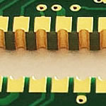
Audio input and output amplifier Aluminum mcpcb aplication
China PCB Manufacturing, Shenzhen PCB Manufacturer, Making Circuit boards
PCB Contract manufacturer, PCB Fabrication, Turnkey assembly services
Buy Print circuit board, customer: /USA/UK/Canada/South Africa...
PCB Supplier Shenzhen, China, PCB Manufacturer, Turnkey services
-
PCBSINO is the Top 5 PCB manufacturer company in China.
PCBSINO do rapid Prototype within 24 hours. our rigid PCB like MCPCB and Rogers PCB, FR4, High TG FR4, Rogers 4003, 4350,Al Aluminum metal Core MCPCB, Al2O3 Ceramic,Taconic,Halogen Free material, CEM-3, Fr2, CEM-1, CEM-2, 94VO, Rogers HF material, Polymide, etc.
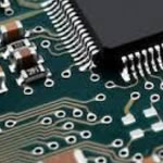
PCBSINO making many type electronic product for our customer, Our turkey services team can source original components part for your project(Digikey/Mouser/RS...), senior Electronic engineer will follow each step of the production to solve any PCB problem and our team will do final function test in PCB house.
Express PCB |
|
Rigid PCB Rapid Prototype,24 hours |
| Fr4 PCB |
|
prototype Lower to 15USD ! |
| Rapid Prototype |
|
Fr4 Rigid PCB Rapid Prototype China, |
MCPCB |
|
MCPCB Manufacturer China, Shenzhen |
| Aluminum PCB: |
|
Aluminum Metal Core PCB manufacturing, Fabrication |
| Aluminum PCB: |
|
single side, double side MCPCB, 0.5-5mm or more |
Rogers 4350B |
|
Rogers 4350,Rogers 4003 Manufacturing |
| Rogers 4350B |
|
Rogers 4350B,4003C PCB Manufacturer |
| Ro4350B |
|
Rogers High Frequency PCB Manufaturing China |
Turnkey Services |
|
Turnkey PCB Assembly Services, |
| Turnkey services |
|
Print circuit board Manufacturing, Turnkey Services |
| Turnkey Assembly |
|
Through Hole PCB components wave soldering Assembly |
Audio input and output amplifier Aluminum mcpcb aplication
-
Audio input and output amplifier Aluminum mcpcb aplication
Aluminum base PCB used:
1. Audio devices: input, output amplifiers, balanced amplifiers, audio amplifier, preamplifier, power amplifier.etc.
2. Power Supply: Switching Regulator,DC / AC converter,SW regulator.
3. Telecommunications electronic equipment: high-frequency electric amplifiers ,Filtering appliance ,Transmitter circuit,etc.
4. Office automation equipment: Electric motor, drives.etc
5. Automotive: Electronic regulator, Ignition, Power Controllers.etc
6. Computer: CPU board ,Floppy drive ,Power Device.etc
7. Power Modules:Converter, solid-state relay ,Power Rectifier bridges,etc
8. Lamps Lighting: with the promotion of energy-saving lamps, Aluminum base PCB , used on LED lights ,begin large-scale application.
Key Specifications/Special Features:
Number of layers: 1
Laminate material: copper
Surface finish: OSP
Copper thickness: 2 oz
Board thickness: 2.0mm (0.078”)
Board size:
Color of mask: white
Flammability: UL 94V-0
Workmanship: compliance with IPC-A-600 and IPC-6012 class II
Single Layer Metal Core PCB
A simple layer single sided MCPCB consists of a metal base (usually aluminum, or copper alloy), Dielectric (non-conducting) Layer, Copper Circuit Layer, IC components and solder mask.
The prepreg dielectric provides excellent heat transfer from the foil and components to the base plate, while maintaining excellent electrical isolation. The base aluminum/copper plate gives the single-sided substrate mechanical integrity, and distributes and transfers the heat to a heat sink, mounting surface or directly to the ambient air.
The Single-Layer MCPCB can be used with surface mount and chip & wire components, and provides much lower thermal resistance than FR4 PWB. The metal core provides lower cost than ceramic substrates, and allows much larger areas than ceramic substrates.
Double Layers Metal Core PCB
Double layers MCPCB is consisting of two layers of copper conductor, put them on same side of metal core (usually aluminum, copper or iron alloy). The metal base is on the bottom of whole MCPCB, which is different from double sided MCPCB(the two copper layers were put on the each side of metal core respectively), and you can only populate SMD on top side.
Different with Single layer MCPCB, 2 layers MCPCB requires an additional pressing step to laminate the imaged thermal conductive laminate and metal core (also known as metal base) together.
Compared with normal FR4, this sturcture need more technology and experience on laminating of two layers together with metal core.
The processing steps of the MCPCB with the metal base embedded in the PCB are comparatively complex as hole plugging is required after primary drilling on the metal base in order to isolate it from the circuitry.
Double Sided Metal Core PCB
It also has same two layers of copper conductor like Double layers MCPCB, but the metal core is in the middle of two conductor, so there're conductors (trace) on both sides of metal core, and were connected to each other by Vias. So we named it "Double sided MCPCB", and you can populated SMD on both top and bottom.
Different with Single layer MCPCB, double sided MCPCB also requires an additional pressing step to laminate the imaged thermal conductive laminate and metal core (also known as metal base) together. But sometimes, some raw Metal Clad material vendor will supply board material which already laminated.
Compared with normal FR4, this sturcture need more technology and experience on laminating of two layers together with metal core.
Multi Layers Metal Core PCB
Just like FR4 PCB, we can also make boards with more than 2 layers of traces and we named it "Multi Layers MCPCB". The structure is similar with FR4 Multi Layers, but it much more complex to make.
You can populated more components on the boards, put signal and ground layer into seperated layers, to achieve better performance in electrical performance.
Compared with normal FR4, this sturcture need more technology and experience on laminating of more than two layers together with metal core and the cost is much higher than 2 layers MCPCBor double sided MCPCB.
Application of MCPCB
Video amplifiers[edit]
Video amplifiers are designed to process video signals and have varying bandwidths depending on whether the video signal is for SDTV, EDTV, HDTV 720p or 1080i/p etc.. The specification of the bandwidth itself depends on what kind of filter is used—and at which point (−1 dB or −3 dB for example) the bandwidth is measured. Certain requirements for step response and overshoot are necessary for an acceptable TV image.[27]
Microwave amplifiers[edit]
Traveling wave tube amplifiers (TWTAs) are used for high power amplification at low microwave frequencies. They typically can amplify across a broad spectrum of frequencies; however, they are usually not as tunable as klystrons.[28]
Klystrons are specialized linear-beam vacuum-devices, designed to provide high power, widely tunable amplification of millimetre and sub-millimetre waves. Klystrons are designed for large scale operations and despite having a narrower bandwidth than TWTAs, they have the advantage of coherently amplifying a reference signal so its output may be precisely controlled in amplitude, frequency and phase.
Solid-state devices are used such as GaAs FETs, IMPATT diodes, and others, especially at lower microwave frequencies and power levels on the order of watts.
The maser is a non-electronic microwave amplifier.
Musical instrument amplifiers[edit]
Instrument amplifiers are a range of audio power amplifiers used to increase the sound level of musical instruments, for example guitars, during performances.
Classification of amplifier stages and systems[edit]
Common terminal[edit]
One set of classifications for amplifiers is based on which device terminal is common to both the input and the output circuit. In the case of bipolar junction transistors, the three classes are common emitter, common base, and common collector. For field-effect transistors, the corresponding configurations are common source, common gate, and common drain; for vacuum tubes, common cathode, common grid, and common plate.
The common emitter (or common source, common cathode, etc.) is most often configured to provide amplification of a voltage applied between base and emitter, and the output signal taken between collector and emitter is inverted, relative to the input. The common collector arrangement applies the input voltage between base and collector, and to take the output voltage between emitter and collector. This causes negative feedback, and the output voltage tends to follow the input voltage. This arrangement is also used as the input presents a high impedance and does not load the signal source, though the voltage amplification is less than one. The common-collector circuit is, therefore, better known as an emitter follower, source follower, or cathode follower.
Unilateral or bilateral[edit]
An amplifier whose output exhibits no feedback to its input side is described as 'unilateral'. The input impedance of a unilateral amplifier is independent of load, and output impedance is independent of signal source impedance.[29]
An amplifier that uses feedback to connect part of the output back to the input is a bilateral amplifier. Bilateral amplifier input impedance depends on the load, and output impedance on the signal source impedance. All amplifiers are bilateral to some degree; however they may often be modeled as unilateral under operating conditions where feedback is small enough to neglect for most purposes, simplifying analysis (see the common base article for an example).
Inverting or non-inverting[edit]
Another way to classify amplifiers is by the phase relationship of the input signal to the output signal. An 'inverting' amplifier produces an output 180 degrees out of phase with the input signal (that is, a polarity inversion or mirror image of the input as seen on an oscilloscope). A 'non-inverting' amplifier maintains the phase of the input signal waveforms. An emitter follower is a type of non-inverting amplifier, indicating that the signal at the emitter of a transistor is following (that is, matching with unity gain but perhaps an offset) the input signal. Voltage follower is also non inverting type of amplifier having unity gain.
This description can apply to a single stage of an amplifier, or to a complete amplifier system.
Function[edit]
Other amplifiers may be classified by their function or output characteristics. These functional descriptions usually apply to complete amplifier systems or sub-systems and rarely to individual stages.
A servo amplifier indicates an integrated feedback loop to actively control the output at some desired level. A DC servo indicates use at frequencies down to DC levels, where the rapid fluctuations of an audio or RF signal do not occur. These are often used in mechanical actuators, or devices such as DC motors that must maintain a constant speed or torque. An AC servo amp. can do this for some AC motors.
A linear amplifier responds to different frequency components independently, and does not generate harmonic distortion or intermodulation distortion. No amplifier can provide perfect linearity (even the most linear amplifier has some nonlinearities, since the amplifying devices—transistors or vacuum tubes—follow nonlinear power laws such as square-laws and rely on circuitry techniques to reduce those effects).
A nonlinear amplifier generates significant distortion and so changes the harmonic content; there are situations where this is useful. Amplifier circuits intentionally providing a non-linear transfer function include:
a device like a silicon controlled rectifier or a transistor used as a switch may be employed to turn either fully on or off a load such as a lamp based on a threshold in a continuously variable input.
a non-linear amplifier in an analog computer or true RMS converter for example can provide a special transfer function, such as logarithmic or square-law.
a Class C RF amplifier may be chosen because it can be very efficient—but is non-linear. Following such an amplifier with a so-called tank tuned circuit can reduce unwanted harmonics (distortion) sufficiently to make it useful in transmitters, or some desired harmonic may be selected by setting the resonant frequency of the tuned circuit to a higher frequency rather than fundamental frequency in frequency multiplier circuits.
Automatic gain control circuits require an amplifier's gain be controlled by the time-averaged amplitude so that the output amplitude varies little when weak stations are being received. The non-linearities are assumed arranged so the relatively small signal amplitude suffers from little distortion (cross-channel interference or intermodulation) yet is still modulated by the relatively large gain-control DC voltage.
AM detector circuits that use amplification such as anode-bend detectors, precision rectifiers and infinite impedance detectors (so excluding unamplified detectors such as cat's-whisker detectors), as well as peak detector circuits, rely on changes in amplification based on the signal's instantaneous amplitude to derive a direct current from an alternating current input.
Operational amplifier comparator and detector circuits.
A wideband amplifier has a precise amplification factor over a wide frequency range, and is often used to boost signals for relay in communications systems. A narrowband amp amplifies a specific narrow range of frequencies, to the exclusion of other frequencies.
An RF amplifier amplifies signals in the radio frequency range of the electromagnetic spectrum, and is often used to increase the sensitivity of a receiver or the output power of a transmitter.[30]
An audio amplifier amplifies audio frequencies. This category subdivides into small signal amplification, and power amps that are optimised to driving speakers, sometimes with multiple amps grouped together as separate or bridgeable channels to accommodate different audio reproduction requirements. Frequently used terms within audio amplifiers include:
Preamplifier (preamp.), which may include a phono preamp with RIAA equalization, or tape head preamps with CCIR equalisation filters. They may include filters or tone control circuitry.
Power amplifier (normally drives loudspeakers), headphone amplifiers, and public address amplifiers.
Stereo amplifiers imply two channels of output (left and right), though the term simply means "solid" sound (referring to three-dimensional)—so quadraphonic stereo was used for amplifiers with four channels. 5.1 and 7.1 systems refer to Home theatre systems with 5 or 7 normal spatial channels, plus a subwoofer channel.
Buffer amplifiers, which may include emitter followers, provide a high impedance input for a device (perhaps another amplifier, or perhaps an energy-hungry load such as lights) that would otherwise draw too much current from the source. Line drivers are a type of buffer that feeds long or interference-prone interconnect cables, possibly with differential outputs through twisted pair cables.
Interstage coupling method[edit]
See also: multistage amplifiers
Amplifiers are sometimes classified by the coupling method of the signal at the input, output, or between stages. Different types of these include:
Resistive-capacitive (RC) coupled amplifier, using a network of resistors and capacitors
By design these amplifiers cannot amplify DC signals as the capacitors block the DC component of the input signal. RC-coupled amplifiers were used very often in circuits with vacuum tubes or discrete transistors. In the days of the integrated circuit a few more transistors on a chip are much cheaper and smaller than a capacitor.
Inductive-capacitive (LC) coupled amplifier, using a network of inductors and capacitors
This kind of amplifier is most often used in selective radio-frequency circuits.
Transformer coupled amplifier, using a transformer to match impedances or to decouple parts of the circuits
Quite often LC-coupled and transformer-coupled amplifiers cannot be distinguished as a transformer is some kind of inductor.
Direct coupled amplifier, using no impedance and bias matching components
This class of amplifier was very uncommon in the vacuum tube days when the anode (output) voltage was at greater than several hundred volts and the grid (input) voltage at a few volts minus. So they were only used if the gain was specified down to DC (e.g., in an oscilloscope). In the context of modern electronics developers are encouraged to use directly coupled amplifiers whenever possible. In FET and CMOS technologies direct coupling is dominant since gates of MOSFETs theoretically pass no current through themselves. Therefore, DC component of the input signals is automatically filtered.
Frequency range[edit]
Depending on the frequency range and other properties amplifiers are designed according to different principles.
Frequency ranges down to DC are only used when this property is needed. Amplifiers for direct current signals are vulnerable to minor variations in the properties of components with time. Special methods, such as chopper stabilized amplifiers are used to prevent objectionable drift in the amplifier's properties for DC. "DC-blocking" capacitors can be added to remove DC and sub-sonic frequencies from audio amplifiers.
Depending on the frequency range specified different design principles must be used. Up to the MHz range only "discrete" properties need be considered; e.g., a terminal has an input impedance.
As soon as any connection within the circuit gets longer than perhaps 1% of the wavelength of the highest specified frequency (e.g., at 100 MHz the wavelength is 3 m, so the critical connection length is approx. 3 cm) design properties radically change. For example, a specified length and width of a PCB trace can be used as a selective or impedance-matching entity. Above a few hundred MHz, it gets difficult to use discrete elements, especially inductors. In most cases, PCB traces of very closely defined shapes are used instead (stripline techniques).
The frequency range handled by an amplifier might be specified in terms of bandwidth (normally implying a response that is 3 dB down when the frequency reaches the specified bandwidth), or by specifying a frequency response that is within a certain number of decibels between a lower and an upper frequency (e.g. "20 Hz to 20 kHz plus or minus 1 dB").
Power amplifier classes[edit]
Power amplifier circuits (output stages) are classified as A, B, AB and C for analog designs—and class D and E for switching designs. The power amplifier classes are based on the proportion of each input cycle (conduction angle) during which an amplifying device passes current.[31] The image of the conduction angle derives from amplifying a sinusoidal signal. If the device is always on, the conducting angle is 360°. If it is on for only half of each cycle, the angle is 180°. The angle of flow is closely related to the amplifier power efficiency.
Example amplifier circuit[edit]
A practical amplifier circuit
The practical amplifier circuit to the right could be the basis for a moderate-power audio amplifier. It features a typical (though substantially simplified) design as found in modern amplifiers, with a class-AB push–pull output stage, and uses some overall negative feedback. Bipolar transistors are shown, but this design would also be realizable with FETs or valves.
The input signal is coupled through capacitor C1 to the base of transistor Q1. The capacitor allows the AC signal to pass, but blocks the DC bias voltage established by resistors R1 and R2 so that any preceding circuit is not affected by it. Q1 and Q2 form a differential amplifier (an amplifier that multiplies the difference between two inputs by some constant), in an arrangement known as a long-tailed pair. This arrangement is used to conveniently allow the use of negative feedback, which is fed from the output to Q2 via R7 and R8.
The negative feedback into the difference amplifier allows the amplifier to compare the input to the actual output. The amplified signal from Q1 is directly fed to the second stage, Q3, which is a common emitter stage that provides further amplification of the signal and the DC bias for the output stages, Q4 and Q5. R6 provides the load for Q3 (a better design would probably use some form of active load here, such as a constant-current sink). So far, all of the amplifier is operating in class A. The output pair are arranged in class-AB push–pull, also called a complementary pair. They provide the majority of the current amplification (while consuming low quiescent current) and directly drive the load, connected via DC-blocking capacitor C2. The diodes D1 and D2 provide a small amount of constant voltage bias for the output pair, just biasing them into the conducting state so that crossover distortion is minimized. That is, the diodes push the output stage firmly into class-AB mode (assuming that the base-emitter drop of the output transistors is reduced by heat dissipation).
This design is simple, but a good basis for a practical design because it automatically stabilises its operating point, since feedback internally operates from DC up through the audio range and beyond. Further circuit elements would probably be found in a real design that would roll-off the frequency response above the needed range to prevent the possibility of unwanted oscillation. Also, the use of fixed diode bias as shown here can cause problems if the diodes are not both electrically and thermally matched to the output transistors – if the output transistors turn on too much, they can easily overheat and destroy themselves, as the full current from the power supply is not limited at this stage.
A common solution to help stabilise the output devices is to include some emitter resistors, typically one ohm or so. Calculating the values of the circuit's resistors and capacitors is done based on the components employed and the intended use of the amp.
Notes on implementation[edit]
LED lights:High-current LED, Spotlight, high-current PCB
Industrial power equipment:High-power transistors, transistor arrays, push-pull or totem pole output circuit (to tem pole), solid-state relay, pulse motor driver, the engine Computing amplifiers (Operational amplifier for serro-motor), pole-changing device (Inverter)
Cars: firing implement, power regulator, exchange converters, power controllers, variable optical system
Power: voltage regulator series, switching regulator, DC-DC converters
OA: Printer driver, large electronic display substrate, thermal print head
Audio: input - output amplifier, balanced amplifier, pre-shield amplifier, audio amplifier, power amplifier
Others: Semiconductor thermal insulation board, IC arrays, resistor arrays, Ics carrier chip, heat sink, solar cell substrates, semiconductor refrigeration device
Figure 3 shows a differential implementation of the output transistors and LC filter in a Class D amplifier. This H-bridge has two half-bridge switching circuits that supply pulses of opposite polarity to the filter, which comprises two inductors, two capacitors, and the speaker. Each half-bridge contains two output transistors—a high-side transistor (MH) connected to the positive power supply, and a low-side transistor (ML) connected to the negative supply. The diagrams here show high-side pMOS transistors. High-side nMOS transistors are often used to reduce size and capacitance, but special gate-drive techniques are required to control them (Further Reading 1).
Full H-bridge circuits generally run from a single supply (VDD), with ground used for the negative supply terminal (VSS). For a given VDD and VSS, the differential nature of the bridge means that it can deliver twice the output signal and four times the output power of single-ended implementations. Half-bridge circuits can be powered from bipolar power supplies or a single supply, but the single-supply version imposes a potentially harmful dc bias voltage, VDD/2, across the speaker, unless a blocking capacitor is added.
The power supply voltage buses of half-bridge circuits can be “pumped” beyond their nominal values by large inductor currents from the LC filter. The dV/dt of the pumping transient can be limited by adding large decoupling capacitors between VDD and VSS. Full-bridge circuits do not suffer from bus pumping, because inductor current flowing into one of the half-bridges flows out of the other one, creating a local current loop that minimally disturbs the power supplies.
Applications for audio amplifiers include home audio systems, concert and theatrical sound reinforcement and public address systems.
Video amplifiers can be used to improve the quality and resolution of TVs, DVRs, computer monitors, set-top boxes and video signals from security cameras. They can also be used in order to improve the video quality of screens installed in vehicles and smart phones. In addition, video amplifiers are used in video switchers and routers and as a pulse amplifier in communications.
Variable gain amplifiers are useful in order to tame signals exhibiting a wide dynamic range. A good example would be mobile phone receivers.
Operational amps are very widely used in electronic devices and can be found in several consumers, industrial and scientific applications and are widely used as building blocks for circuit design.
Common applications for programmable gain amplifiers are motor control, signal and sensor conditioning, as well as in bar code readers and digital cameras.
Low noise amplifiers are used in various applications such as ISM radios, cellular and PCS handsets, wireless LANs, wireless Data, GPS receivers, cordless phones and automotive remote keyless entry devices.
High speed amplifiers are found in several applications including battery-powered and high-speed systems, communication & video test equipment, portable medical instrumentation and radar and sonar applications.
Differential amplifiers can be found in many circuits that use series negative feedback. A common application is the control of servos or motor and for signal amplification applications.
Thermal conductivity:
Single layer metal core PCB
Simple layer single sided MCPCB consists of metal base (usually aluminum, or copper alloy)
Dielectric (non-conducting) layer, copper circuit layer, IC components and solder mask
Prepare dielectric provides excellent heat transfer from foil and components to base plate, while maintaining excellent electrical isolation
Base aluminum/copper plate gives single-sided substrate mechanical integrity and distributes and transfers heat to a heat sink, mounting surface or directly to ambient air
Single-layer MCPCB can be used with surface mount and chip, wire components and provides much lower thermal resistance than FR4 PWB
Metal core provides lower cost than ceramic substrates and allows much larger areas than ceramic substrates
Applications:
LED lights: high-current LED, spotlight, high-current PCB
Industrial power equipment: high-power transistors, transistor arrays, push-pull or totem pole output circuit (to tem pole), solid-state relay, pulse motor driver, engine computing amplifiers (operational amplifier for serro-motor), pole-changing device (inverter)
Cars: firing implement, power regulator, exchange converters, power controllers and variable optical system
Power: voltage regulator series, switching regulator, DC-DC converters
OA: printer driver, large electronic display substrate, thermal print head
Audio: input-output amplifier, balanced amplifier, pre-shield amplifier, audio amplifier and power amplifier
Others: semiconductor thermal insulation board, IC arrays, resistor arrays, ICS carrier chip, heat sink, solar cell substrates and semiconductor refrigeration device
For furhter information, please feel free to contact us, www.pcbsino.com