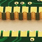
High power switch regulator Aluminum mcpcb aplication
China PCB Manufacturing, Shenzhen PCB Manufacturer, Making Circuit boards
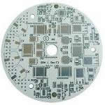
PCB Contract manufacturer, PCB Fabrication, Turnkey assembly services
Buy Print circuit board, customer: /USA/UK/Canada/South Africa...
PCB Supplier Shenzhen, China, PCB Manufacturer, Turnkey services
-
PCBSINO is the Top 5 PCB manufacturer company in China.
PCBSINO do rapid Prototype within 24 hours. our rigid PCB like MCPCB and Rogers PCB, FR4, High TG FR4, Rogers 4003, 4350,Al Aluminum metal Core MCPCB, Al2O3 Ceramic,Taconic,Halogen Free material, CEM-3, Fr2, CEM-1, CEM-2, 94VO, Rogers HF material, Polymide, etc.
PCBSINO making many type electronic product for our customer, Our turkey services team can source original components part for your project(Digikey/Mouser/RS...), senior Electronic engineer will follow each step of the production to solve any PCB problem and our team will do final function test in PCB house.
Express PCB |
|
Rigid PCB Rapid Prototype,24 hours |
| Fr4 PCB |
|
prototype Lower to 15USD ! |
| Rapid Prototype |
|
Fr4 Rigid PCB Rapid Prototype China, |
MCPCB |
|
MCPCB Manufacturer China, Shenzhen |
| Aluminum PCB: |
|
Aluminum Metal Core PCB manufacturing, Fabrication |
| Aluminum PCB: |
|
single side, double side MCPCB, 0.5-5mm or more |
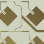
Rogers 4350B |
|
Rogers 4350,Rogers 4003 Manufacturing |
| Rogers 4350B |
|
Rogers 4350B,4003C PCB Manufacturer |
| Ro4350B |
|
Rogers High Frequency PCB Manufaturing China |
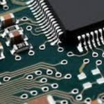
Turnkey Services |
|
Turnkey PCB Assembly Services, |
| Turnkey services |
|
Print circuit board Manufacturing, Turnkey Services |
| Turnkey Assembly |
|
Through Hole PCB components wave soldering Assembly |
High power switch regulator Aluminum mcpcb aplication
-
High power switch regulator Aluminum mcpcb aplication
Aluminum based PCB, also named Aluminium PCB, metal clad(MCPCB) PCB, insulated metal substrate(IMS or IMPCB) PCB, thermally conductive PCBs, etc. It is generally including single layer, double layer and multi layer.
Operating theory:
The power device surface mounting on circuit layer, it is ideally suited for the mounting of high power light emitting diodes (LEDs) easily dissipating the heat generated by power devices.
Aluminum based PCB used:
Aluminum base PCB used:
1. Audio devices: input, output amplifiers, balanced amplifiers, audio amplifier, preamplifier, power amplifier.etc.
2. Power Supply: Switching Regulator,DC / AC converter,SW regulator.
3. Telecommunications electronic equipment: high-frequency electric amplifiers ,Filtering appliance ,Transmitter circuit,etc.
4. Office automation equipment: Electric motor, drives.etc
5. Automotive: Electronic regulator, Ignition, Power Controllers.etc
6. Computer: CPU board ,Floppy drive ,Power Device.etc
7. Power Modules:Converter, solid-state relay ,Power Rectifier bridges,etc
8. Lamps Lighting: with the promotion of energy-saving lamps, Aluminum base PCB , used on LED lights ,begin
Metal Core PCB means the core (base) material for PCB is the metal, not the normal FR4/CEM1-3, etc. and currently the most common metal used for MCPCB manufacturer are Aluminum, Copper and steel alloy. Aluminum has good heat transferring and dissipation ability, but yet relatively cheaper; copper has even better performance but relatively more expensive, and steel can be divided into normal steel and stainless steel. It more rigid than both aluminum and copper, but thermal conductivity is lower than them too. People will choose their own base/core material according to their different application.
Generally speaking, aluminum is the most economic option considering thermal conductivity, rigidness, and cost. Therefore, the base/core material of normal Metal Core PCB are made of aluminum. In our company, if not special request, or notes, the metal core refer will be aluminum, then MCPCB will means Aluminum Core PCB. If you need Copper Core PCB, Steel Core PCB, or Stainless steel core PCB, you should add special notes in drawing.
Sometimes people will use abbreviation “MCPCB”, instead of the full name as Metal Core PCB, or Metal Core Printed Circuit Board. And also used different word refers the core/base, so you will also see different name of Metal Core PCB, such as Metal PCB, Metal Base PCB, Metal Backed PCB, Metal Clad PCB and Metal Core Board and so on.
MCPCBs are used instead of traditional FR4 or CEM3 PCBs because of the ability to efficiently dissipate heat away from the components. This is achieved by using a Thermally Conductive Dielectric Layer.
The main difference between a FR4 board and MCPCB is the thermal conductivity dielectric material in the MCPCB. This acts as a thermal bridge between the IC components and metal backing plate. Heat is conducted from the package through the metal core to an additional heat sink. On the FR4 board the heat remains stagnant if not transferred by a topical heatsink. According to Avago’s white paper a MCPCB with a 1W LED remained near an ambient of 25C, while the same 1W LED on a FR4 board reached 12C over ambient. LED PCB always be produced with Aluminum core, but sometimes steel core PCB also be used.
A simple layer single sided MCPCB consists of a metal base (usually aluminum, or copper alloy), Dielectric (non-conducting) Layer, Copper Circuit Layer, IC components and solder mask.
The prepreg dielectric provides excellent heat transfer from the foil and components to the base plate, while maintaining excellent electrical isolation. The base aluminum/copper plate gives the single-sided substrate mechanical integrity, and distributes and transfers the heat to a heat sink, mounting surface or directly to the ambient air.
The Single-Layer MCPCB can be used with surface mount and chip & wire components, and provides much lower thermal resistance than FR4 PWB. The metal core provides lower cost than ceramic substrates, and allows much larger areas than ceramic substrates.
Double Layers Metal Core PCB
Just like FR4 PCB, we can also make boards with more than 2 layers of traces and we named it "Multi Layers MCPCB". The structure is similar with FR4 Multi Layers, but it much more complex to make.
You can populated more components on the boards, put signal and ground layer into seperated layers, to achieve better performance in electrical performance.
Compared with normal FR4, this sturcture need more technology and experience on laminating of more than two layers together with metal core and the cost is much higher than 2 layers MCPCBor double sided MCPCB.
Application of MCPCB
Metal Core PCB means the core (base) material for PCB is the metal, not the normal FR4/CEM1-3, etc. and currently the most common metal used for MCPCB manufacturer are Aluminum, Copper and steel alloy. Aluminum has good heat transferring and dissipation ability, but yet relatively cheaper; copper has even better performance but relatively more expensive, and steel can be divided into normal steel and stainless steel. It more rigid than both aluminum and copper, but thermal conductivity is lower than them too. People will choose their own base/core material according to their different application.
Generally speaking, aluminum is the most economic option considering thermal conductivity, rigidness, and cost. Therefore, the base/core material of normal Metal Core PCB are made of aluminum. In our company, if not special request, or notes, the metal core refer will be aluminum, then MCPCB will means Aluminum Core PCB. If you need Copper Core PCB, Steel Core PCB, or Stainless steel core PCB, you should add special notes in drawing.
Sometimes people will use abbreviation "MCPCB", instead of the full name as Metal Core PCB, or Metal Core Printed Circuit Board. And also used different word refers the core/base, so you will also see different name of Metal Core PCB, such as Metal PCB, Metal Base PCB, Metal Backed PCB, Metal Clad PCB and Metal Core Board and so on.
This is the FemtoBuck, a small-size single-output constant current LED driver. Each FemtoBuck has the capability to dim a single high-power channel of LEDs from 0-350mA at up to 36V while the dimming control can be either accessed via PWM or analog signal from 0-2.5V. This board is based off of the PicoBuck LED Driver, developed in collaboration with Ethan Zonca, except instead of blending three different LEDs on three different channels the FemtoBuck controls just one.
DC-DC Buck Step-down Regulator Converter 4.2~40v to 3V 3.3V 5V 9V 12V 24V Module
Brand New
RMB 5.30
Buy It Now
Free international shipping
938 sold
From Hong Kong
DC-DC 3.3V 5V 9V 12V 3A Adjustable Buck Step Down Voltage Regulator Power Module
Brand New
RMB 5.30
Buy It Now
Free international shipping
384 sold
From Hong Kong
Tin the Tip: Trying to solder without a tinned tip is futile. To properly tin the tip of an iron apply solder to the tip and coat it thick. The next step is to wipe off the excess solder with a wet sponge and finally reapply a little amount of solder to the tip again.
Cleaning the soldering surface
Clean Solder Surface: Obviously the more clean the surface, the better. Ideally make sure the surface is free of dirt, dust, epoxy or anything else.
Applications of MCPCBs
Following are the few applications using MCPCBs:
LED Lights: Spotlights, high-current PCBs, high-current LEDs, street safety applications, and all applications using LEDs.
Cars: Power regulators, firing implement, exchange converters, variable optical systems, and motors used in electric and hybrid cars.
Power Supply Devices: DC-DC Converters, voltage regulators, high density power conversion, and switching regulators.
Audio Devices: Balanced, input-output, audio, power, and pre-shield amplifiers.
Other Electronic Devices: IC arrays, thermal insulation boards for semiconductors, ICs carrier chips, solar cell substrates, heat sinks, and semiconductor refrigeration devices.
Home Appliances: Flat panel displays, motor controls,
OA Devices: Large electronic display substrates, thermal print heads, and printer drivers.
Benefits of Metal Core PCBs
Following benefits of metal core PCBs make them ideal for different industrial applications:
Enigma Interconnect manufactures MCPCB’s for customers that require thermal conductivity which is assisted by a metal core. Ideal for use in LED technology and for high power transistors, the conductive cooling provided by MCPCB’s are an ideal production option that increase performance and product life.
The metal core of a thermal PCB can be copper, a mixture of alloys or aluminum (which is most common). Applications that generate a large amount of heat often cannot adequately be cooled using traditional methods. As a result, metal core PBC’s have become an ideal design and production option due to their conductive cooling because they can transfer heat 8-9 times faster than FR4 PCB’s.
High Thermal Conductivity: The standard PCBs with FR4 and CEM3 have weak inter-layer insulation, and low thermal conductivity. If heat is not properly dissipated, the internal temperature may raise, and affect the internal components. Metal PCBs made from aluminum have excellent thermal conductivity, which helps keep the internal components safe.
Good Dimensional Stability: The metal core PCB exhibits good dimensional stability when compared to FR4 or CEM3 PCB. When aluminum PCB is heated to a temperature from 30 degree C to 140~150 degree C, its dimension expands between 2.5-3%.
High Thermal Expansibility: The Coefficient of Thermal Expansion (CTE) is the term used to describe expansion or contraction of a substance under the temperature. Aluminum and copper have high CTE than the normal FR4, and thermal conductivity is 0.8~3.0 W/c.K.
Tinning a soldering pad
Tin the Surfaces (Wires, Solder Pad or PCB): In our video we show an example of soldering wires to a Cree LED star, but before making the final connection the wire leads are first tinned. Similar to tinning an iron, the wires get a thin layer of solder applied to them; it’s important that the solder sticks to the wire. Remember the suggestion above about the rosin being in the middle of the solder; using the middle of the solder helps it stick to the wire better. Also, in the example in our video the solder pad surface getting tinned too. Apply a tinned tip iron to the solder pad and begin applying solder to the pad. The solder should flow evenly over the entire pad and once it does remove the iron and let the solder firm up.
Final Connection: At this point all the hard work is done. With a nicely tinned tip and surface, simply touch the two pieces being solder together with the iron. The solder on each surface should flow; quickly remove the iron and when the solder hardens, both the components should be soldered together.
DC-DC Boost Converter 3.3v 5v 9v 12v 2A Adjustable Step Up Power Supply Module
Brand New
RMB 5.30
Buy It Now
Free international shipping
287 sold
For the FemtoBuck, we’ve increased the voltage ratings on the parts to allow the input voltage to cover the full 36V range of the AL8805 driver. Since the FemtoBuck is a constant current driver, the current drawn from the supply will drop as supply voltage rises. In general, efficiency of the FemtoBuck is around 95%, depending on the input voltage. On board each FemtoBuck you will find two inputs for both power input and dimming control pins and an area to install a 3.5mm screw terminal. Finally at either side of the board you will find small indents or “ears” which will allow you to use a zip tie to secure the wires to the board after soldering them down. This version of the FemtoBuck is equipped with a small solder jumper that can be closed with a glob of solder to double the output current from 330mA to 660mA.
MCPCBs are used instead of traditional FR4 or CEM3 PCBs because of the ability to efficiently dissipate heat away from the components. This is achieved by using a Thermally Conductive Dielectric Layer.
The main difference between a FR4 board and MCPCB is the thermal conductivity dielectric material in the MCPCB. This acts as a thermal bridge between the IC components and metal backing plate. Heat is conducted from the package through the metal core to an additional heat sink. On the FR4 board the heat remains stagnant if not transferred by a topical heatsink. According to Avago's white paper (AV01- 0615EN.pdf) a MCPCB with a 1W LED remained near an ambient of 25C, while the same 1W LED on a FR4 board reached 12C over ambient. LED PCB always be produced with Aluminum core, but sometimes steel core PCB also be used.
LED lights:High-current LED, Spotlight, high-current PCB
Industrial power equipment:High-power transistors, transistor arrays, push-pull or totem pole output circuit (to tem pole), solid-state relay, pulse motor driver, the engine Computing amplifiers (Operational amplifier for serro-motor), pole-changing device (Inverter)
Cars: firing implement, power regulator, exchange converters, power controllers, variable optical system
Power: voltage regulator series, switching regulator, DC-DC converters
OA: Printer driver, large electronic display substrate, thermal print head
Audio: input - output amplifier, balanced amplifier, pre-shield amplifier, audio amplifier, power amplifier
Others: Semiconductor thermal insulation board, IC arrays, resistor arrays, Ics carrier chip, heat sink, solar cell substrates, semiconductor refrigeration device
Advantage:
1. Aluminium PCB & LED PCB factory directly
2. Aluminium PCB & LED PCB Have the comprehensive quality control system
3. Aluminium PCB & LED PCB good price
4. Aluminium PCB & LED PCB quick turn Delivery time from 48hours.
5. Aluminium PCB& LED PCBcertification(ISO/UL E354810/RoHS).
6. 8 years experience in exporting service
7. Aluminium PCB& LED PCB is no MOQ.
8. PCB is high quality.Strict through theAOI(Automated Optical Inspection),QA/QC,fly porbe ,Etesting
Double layers MCPCB is consisting of two layers of copper conductor, put them on same side of metal core (usually aluminum, copper or iron alloy). The metal base is on the bottom of whole MCPCB, which is different from double sided MCPCB(the two copper layers were put on the each side of metal core respectively), and you can only populate SMD on top side.
Different with Single layer MCPCB, 2 layers MCPCB requires an additional pressing step to laminate the imaged thermal conductive laminate and metal core (also known as metal base) together.
Compared with normal FR4, this sturcture need more technology and experience on laminating of two layers together with metal core.
The processing steps of the MCPCB with the metal base embedded in the PCB are comparatively complex as hole plugging is required after primary drilling on the metal base in order to isolate it from the circuitry.
Advantage of MCPCB
1.heat dissipation
Some LEDs dissipate between 2-5W of heat and failures occur when the heat from a LED is not properly removed; a LED’s light output is reduced as well as degradation when the heat remains stagnant in the LED package. The purpose of a MCPCB is to efficiently remove the heat from all topical IC’s (not just LEDs). The aluminum base and thermally conductive dielectric layer act as bridges between the IC’s and heat sink. One single heat sink is mounted directly to the aluminum base eliminating the need for multiple heat sinks on top of the surface mounted components.
2. thermal expansion
Thermal expansion and contraction is the common nature of the substance, different CTE is different in thermal expansion. As its own characterics, aluminum and copper have unique advance than normal FR4, thermal conductivity can be 0.8~3.0 W/c.K.
3. dimensional stability
It is clear that the size of the metal-based printed circuit board more stable than insulating materials. The size change of 2.5 ~ 3.0% when Aluminum PCB and aluminum sandwich panels was heated from 30 ℃ to 140 ~ 150 ℃.
large-scale application.
1. Single-sided Aluminium pcb
Aluminium PCB (Metal Core PCB for LED Lighting)
Single-Sided board ( SSB)
Base-material: Aluminium Base material
Board thickness: 1.6MM
Solder mask Color: White TaiYo
Silkscreen: Black
Surface Finish: HAL Lead Free
Keyword: Aluminium PCB︱Aluminum PCB Manufacturer︱IMS MPCB, MCPCB︱Metal core PCB︱Aluminium based PCB assembly︱LED lighting PCB︱Copper base board︱Al PCB︱Bergquist Aluminum pcb︱MCPCB supplier
For furhter information, please feel free to contact us, www.pcbsino.com